The laser marking market is characterised by an increasing need to mark or texture uneven surfaces such as curved, inclined and stepped surfaces, freeform objects or recessed surfaces. Traditional laser markers and integrated machines are unfortunately limited to a flat working field, which can potentially be adapted for simple inclined planes or cylindrical surfaces by rotating the part during marking. For a long time, the only way to mark more complex shaped surfaces was to use expensive and complexly programmed robotics and five-axis machines.
 Coherent has developed an automated "smart" solution called SmartMap 3D that combines new hardware and software - specifically the proven method of fast variable focusing and new 3D machine vision, all under the control of powerful VLM (Visual Laser Marker) marking software. This easy-to-use combination not only simplifies the entire process, but also eliminates the cost and time of implementing precise fixing, clamping or positioning of the part. Because the VLM is independent of the laser type, SmartMap 3D can be used to produce all different types of laser markers, precision surface finishes (e.g. roughening and texturing) and even black marking stainless steel and aluminum products using ultra-short pulse (USP) lasers. It is available with all Coherent laser markers.
Overcoming the limitations of traditional systems and subsystems
With the exception of marking with high-energy pulses from excimer lasers, most laser marking is based on scanning a focused laser spot across the marked surface, sometimes in combination with continuous or step motion of the marked part. The three main optical components to implement this process are a laser, two galvanometric mirrors for orthogonal scanning of the beam in the X/Y axes and a lens to focus the beam at the correct Z distance, i.e. on the work surface. The lens is usually of the f-theta design. Unlike a conventional spherical focusing lens which has a curved focal plane, the f-theta lens is designed to form a flat focal plane so that the depth of focus of the laser beam is independent of the position across the lens. This is great for flat surfaces that are perpendicular to the direction of the laser beam, but the shallow depth of focus means it is not suitable for 3D marking where the distance from the focusing lens to the surface varies.
Previously, marking 3D surfaces required changing the relative position of the laser system and the part so that the distance between the lens and the surface currently being marked remained constant. This is cumbersome, costly, requires complex programming, and leads to problems in achieving the desired accuracy. SmartMap 3D offers an alternative solution that is much simpler, faster and more economical because it does not require movement of the optical system or the part due to the use of a fast focus module located in the optics. Depending on the specific characteristics of the laser and sensing system, a total range of up to ± 130 mm from the nominal focal length can be achieved. Combining this Z scan with X/Y scanning provides the ability to focus the laser at any point in XYZ space without changing the size or shape of the point.
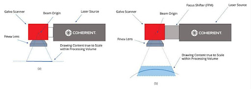
(a) Typical 2D marking setups can produce scale-fidelity content on a flat surface. (b) In SmartMap 3D, the use of the Focus Shift Module (FFM) allows the creation of scale-fidelity markings over the target volume.
SmartMap 3D - a combination of hardware, software and 3D machine vision
Another key element for easy 3D marking is the system's user-friendly Visual Laser Marker (VLM) software environment, which automatically combines the focus module configuration and galvanometer movements needed to create a mark on the workpiece. The user then simply places the marker on the surface using an intuitive graphical user interface. The most intuitive method is called projection mapping, where the mark is defined as a series of points that are all on vectors relative to a fixed point of view. For regular solids such as spheres, cones and cubes, the VLM can produce UV mappings. Here the marker is defined on a series of 2D (flat) surface segments using orthogonal U and V coordinates. This allows the use of existing files such as pdf and dxf documents, and supports flexible content such as QR codes, barcodes and related tags. For complex shaped workpieces or graphics that wrap around parts, more demanding users may prefer to import data from their preferred CAD software and then modify it in VLM. The 3D viewing capabilities in VLM also provide a completely accurate preview of what the part will look like after marking, helping to place markers, visualize the crop angle in false colors, and even adjust machine axis movement - all within the preview window.
The third component of the SmartMap 3D system is the hardware - a line-of-sight machine vision camera that scans each part before marking. This is available in two different wavelengths to accommodate the reflectivity and color of virtually any marking material. The integration of this vision component allows the smart marking software to detect the shape and orientation of the part prior to marking, a three-dimensional point cloud. These results are then compared to the stored CAD model files for the part. The degree of match is expressed as a percentage score. The graphical user interface may optionally display the match rate in a false colour overlay of the camera image(s). The operation may be automated such that if the total match exceeds a minimum score, the machine executes the job. This minimum acceptable score is one of several parameters that the user selects in a stored routine for each type of job. Alternatively, the operator can decide, based on the GUI preview and the score, whether to initiate marking or adjust the position/tilt of the workpiece to achieve a better match. The point cloud can also be converted to a 3D surface and used directly in the VLM when a CAD model is not available.
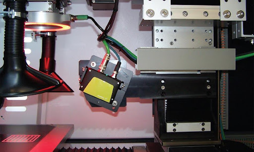
The 3D camera allows the smart marking software to determine the shape and orientation of the parts before marking them as a three-dimensional point cloud.
The smart system is able to adapt to different workpiece locations without having to reposition the laser or workpiece because it takes into account several important parameters, including projection distortion, crop angle, top angle and 3D surface orientation.
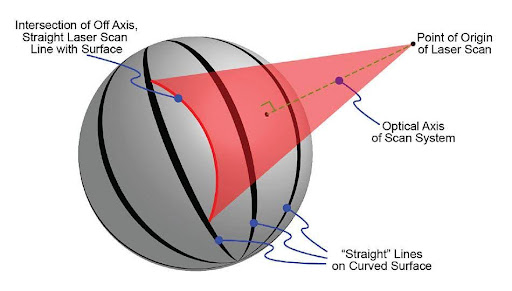
Projection distortion occurs when marking a "straight" line at other than normal incidence on a curved surface.
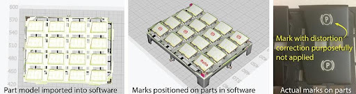
When using Coherent's SmartMap 3D marking system, a CAD model of the part is imported into the software and the user places the desired marks on the part(s). The final results show that distortion correction is required to achieve the correct mark geometry on the workpiece.
Summary
Laser marking offers unique advantages in creating numbers, symbols, logos and other graphics on virtually any type of material. Until now, most laser marking has been limited to flat surfaces or simple shapes. Marking on freeforms has been too complex and costly for many potential applications. This has now completely changed; the advent of the SmartMap 3D marking system brings push-button simplicity and automation, unlocking the full potential of laser marking for industries such as automotive, consumer electronics, appliances and many more.
Source: Coherent.com